Boat Nerd: Boat DC Electrics - Part 2: Wiring your Boat
In Part 1, last issue, you reviewed the fundamentals. Now that you understand some of the basic constructs of electrical work we look at getting down to the exercise of determining what wire to use and how do I connect it? This article will concentrate on the DC side of your vessel. If there is sufficient interest I can look at writing an article on AC wiring and/or shore power.
Wire Types
If you have done any wiring in your house you are probably used to the white jacketed wire containing two or three insulated conductors and an uninsulated ground wire. You will notice that under the insulation the wires are a shiny copper colour and that each wire is one solid conductor. For use at 120/240VAC, your cable will be typically #14, rated at 15A, #12 rated at 20A, or #10 rated at 30A. What do these size measurements mean?
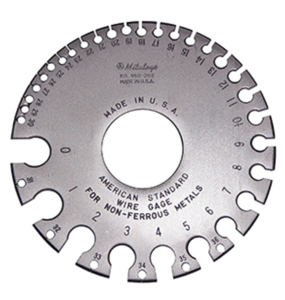
In North America we typically use the American Wire Gauge (AWG) where the numbers run from #30 (very small) to #0000 (very large) for the normal situations you may find yourself in. The wire gets fatter and can carry more current as the wire number goes down. That’s not confusing is it?
You may also hear of the Society of Automotive Engineers (SAE) wire sizing scheme. For the same wire size (eg #14) AWG wire has 10% more copper then the SAE wire. Due to the smaller amount of copper in the wire, SAE designated wire is acceptable in DC circuits but not AC ones.
In Europe (ISO) they have a more sensible system where wire is specified by the cross sectional area (mm2). As the wire gets fatter the mm2 value increases and the wire can carry more current. There are cross reference tables online to allow you to work back and forth. Thus a European cable rated at 2.5mm2 is equivalent to #14AWG and a cable rated at 70mm2 is equivalent to #2/0AWG.
The wire is a shiny copper colour as it is uncoated and un-corroded. When copper is exposed to the air (especially salt air or water) it will start to turn green as it oxidizes. Fun Fact: think of a copper roofed building whereby it starts out a bright shiny copper and how it darkens and turns green as it weathers.
Have you ever tried to break a piece of copper wire by flexing it quickly back and forth? This work hardens the copper and it will soon snap. For use on a boat, which is subject to all sorts of vibration, this would not be a good thing so boat wire is finely stranded to make it much less sensitive to flexing. (Even so you should still support you wiring every 18” or so.)
To further increase boat wires environmental hardiness, it is also tin plated as the tin improves the wires ability to withstand corrosion. When you strip boat cable you will find it’s a silver colour due to this tin plating.
Wire Ampacity
The ability of a wire to carry current is constrained by how much the wire heats up. Any wire has an inherent resistance, as mentioned above, dependent on material, cross section and length. As a current flows through this wire resistance it creates heat at a rate of I squared x R.
Specific Examples
For example if we have 8” of #1/0 battery cable, that has a resistance of about .097 mohm (resistivity of copper x length/cross sectional area or 1.7x10-8 x .2m/35x10-6).
At a current of 100A, we multiply 100 x 100 and divide by .000097 to get a heat loss of 0.97W. That’s pretty negligible in this case. However if we had used a #12 wire what would happen? Now we would be dissipating 8.5W in our 8” wire and it would get very hot. At some point our insulation would melt.
Wire insulation is rated in degrees C. Typically 60, 75, 90 and 105. A wire with a higher temperature rating can carry more current than a wire with a lower temperature rating.
When possible go with 105C rated wire. This temperature rating will be marked on the cable if it is ABYC compliant. If your boat came from a European manufacturer you may find it was built with 60C wiring. The temperature rating also drops if your wire is installed in a wet environment. Eg from 105rC to 75C.
This temperature rating is also affected by ambient temperature (the hotter the wire is to start the less current it can handle), if it is bundled with other current carrying wires or in a shared conduit (again reduces the maximum current the wire can handle as the bundle can’t dissipate the heat as well as a single wire can), and is it in a engine space ( engine spaces are assumed to be at 50C in ABYC standards and this preheating of the cable reduces the ampacity of the wire and accounts for the “inside” and “Outside” columns in a wire sizing table), and how long the load will run for (the longer the run the hotter the cable could get).
If our cable is run at currents that heat the cable substantially, some of this heat will be transferred through to the connected device. Many of these devices are rated at 90C or lower and heat from the cable may cause them to exceed their temperature limit. To mitigate this you may choose to use the 90C or lower columns in the table. This will result in fatter but cooler cables and devices.
The good news is that when we talk about voltage drop in the next installment and look at how to select the required wire size there are tables and programs that take all these factors into account to give you the correct size for your application.
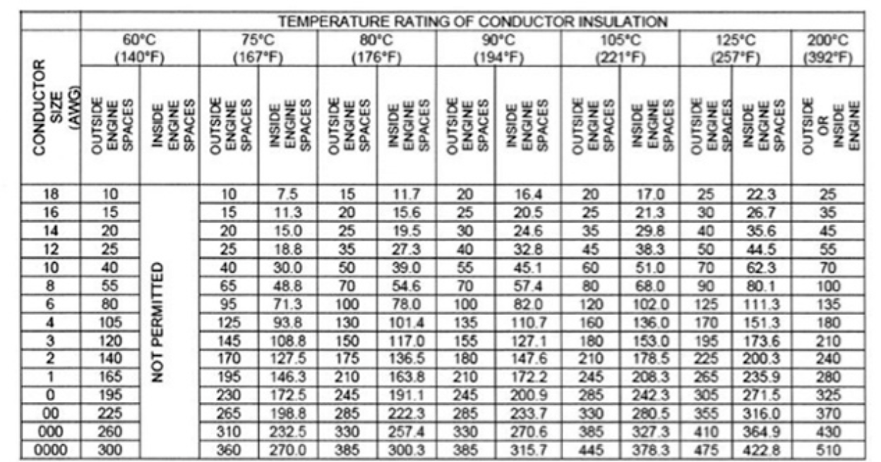
An example of one of these tables taken from ABYC E-11 specification is shown in figure 4. This table is for DC and AC circuits where single conductors, not bundled or placed in conduit are used. If you bundle or run the wiring in a conduit you must use the relevant table.
Next time: Voltage Drop and wire sizing