Ground Plate Installation
Required Tools:
- Drill, bits and countersink
- Grinder
- Reciprocating saw
- Tig or MIG welder and copper welding rods/wire
- common hand and measurement tools
Required Lubricants, Sealants, Adhesives ETC:
- Sealant, polyurethane or polysulfide
- Mineral spirits
- Conductant paste
- Corrosion inhibitor
Parts:
- ¼” thick oxygen free electrical grade copper, remaining dimensions dependent upon application.
- 3/8” bronze flat head fasteners, nuts, washers and lock washers
- 3/8” copper bolt
Relevant ABYC Standard(S)
- E-11, TE-4
Introduction:
The purpose of a ground plate is, or can be, to provide an adequate connection between the vessel’s bonding/grounding system, lightning protection system and SSB radio if equipped, and seawater (when it’s used for SSB radios, it’s referred to as a counterpoise).
It applies equally to both power and sailing vessels. While the “science” of lightning strikes as they relate to small craft is anything but settled, studies indicate that the greatest advantage for strike current dissipation can be gained by providing the longest possible plate edge rather than surface area.
Therefore, a 2-inch wide, 72-inch-long rectangular plate is far more preferable than a 12 inch by 12-inch square plate, even though both are 144 square inches (144 sq. inches is the ABYC required minimum size for a lightning ground plate, but large never hurts). The minimum acceptable thickness for a ground plate is 3/16” however ¼” is preferred.
ABYC’s guidance on ground plates, “A lightning grounding terminal for a boat should consist of a metal surface (copper, copper alloys, stainless steel, aluminum, or lead) that is in contact with the water, having a thickness of at least 3/16 in (5 mm), and an area of at least one square foot (0.1 m2). It should be located as nearly as possible directly below the lightning protective mast in order to minimize any horizontal runs in the primary (main) conductor.”
While other metals are acceptable, copper is preferred for its high conductivity and corrosion resistance.
This Task Sheet applies to FRP hulls. Ground plates are unnecessary on metallic hulls, and may cause delignification issues on timber hulls if the vessel is equipped with a cathodic protection system. Lightning ground, cathodic protection, DC grounding and AC safety grounds should be interconnected; and this is required for ABYC compliance.
For more on bonding and grounding systems see PBB 138 “Bonding Basics” Copper is expensive, so remember to measure twice, and cut once, and always wear eye protection when cutting, grinding or drilling.
Step 1:
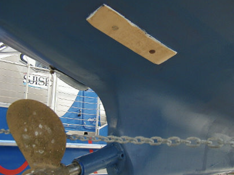
Measure and layout the available space: Choose a location that will remain submerged under all conditions of sail and heel. If the plate will be used as part of the lightning protection system, it should be located close to the base of the mast or primary down-conductor.
The plate should be oriented fore and aft in order to present the least amount of water flow resistance. You must have access to the inside of the vessel where the plate will be through bolted. Determine the size of the plate and establish length and width dimensions.
Step 2:
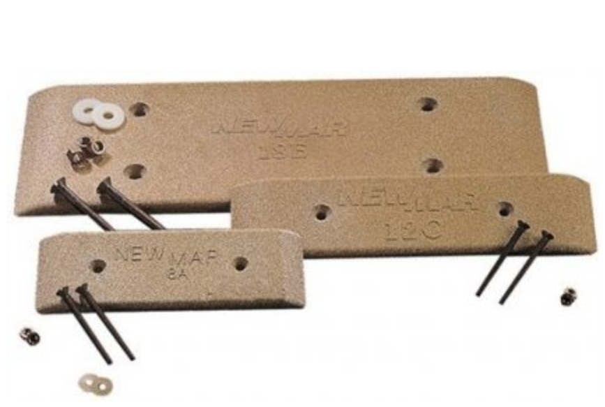
Obtain the plate, cut and drill: Order or take from your stock department a plate of the appropriate dimensions, it should be 100% pure, oxygen free electrical grade copper (McMaster Carr Supply www.mcmaster.com is one supplier for this material, do not use material from stock unless its composition can be verified) that is ¼ inch thick (ABYC Standards allow for a minimum of 3/16” thick plate).
Cut it to fit the prepared dimensions. Bevel the portion of the plate that will face forward to prevent objects from becoming stuck on it once the vessel is returned to service. All of the remaining edges should remain square.
Holes should be drilled to accommodate 3/8” bolts on 12-inch centers. If the plate is more than 4” wide, dual rows of, staggered where possible, fasteners must be used. Never use tapping screws to secure the plate to the vessel’s hull. Drill and countersink holes in the plate to accommodate the fasteners in locations that will not interfere with structures within the vessel. Create a template if necessary.
Step 3:

Dry fit the plate and drill holes in hull – Place the plate up against the hull in the chosen location and mark the locations for the holes that will be drilled (a suitable length of timber or a jack stand and blocking may be used to hold the plate in place). Centering punches may be useful for marking the exact center of each hole.
Drill a ¼” pilot hole through the hull in a location that is at or close to the center of the plate. Make certain there are no critical structures inside the boat in this area, tanks, stringers etc. Go inside the boat and find the hole and verify it is where you believe it should be and using it as a reference point, verify that the additional holes will be clear of any internal structures.
Once this is done, drill the remaining holes at full size (you may wish to choose a slightly larger drill bit, 25/64 or 13/32). Bevel or countersink these holes slightly so they will retain sealant. Once the holes are drilled, hold the plate up to the hull and place fasteners in all of the holes simultaneously to ensure a proper fit. Adjust if necessary and then trace the outline of the plate onto the hull.
NOTE: If the hull is cored, measures must be taken to properly close out the core material at each hole, regardless of core variety. Those instructions can be found in Task Sheet PBB 189 “Installing Hardware in Cored Composites”
Step 4:
Prepare hull and plate for installation: Using a 180-grit sanding disc, grind all bottom paint off the hull until you have exposed either gelcoat or an epoxy barrier coat (every attempt should be made not to grind more than a ½ - 1inch beyond the perimeter of the plate’s footprint). Using the same grit sandpaper, grind the side of the plate that will be placed against the hull.
Step 5:
Weld the bronze fastener to the plate – On the backside or side that will face the hull as well as the front side or side that faces away from the hull, tig weld the copper bolt to the plate. Make certain the weld bead will not interfere with placement of the plate against the hull.
Grind the hull or weld bead if necessary to accommodate. Using a multimeter, check for continuity between this fastener and the plate, resistance should be less than one ohm. Using a letter punch set, or engraver stamp or engrave the outside of the plate adjacent to this fastener with the words, THIS FASTENER WELDED (the weld bead should be obvious).
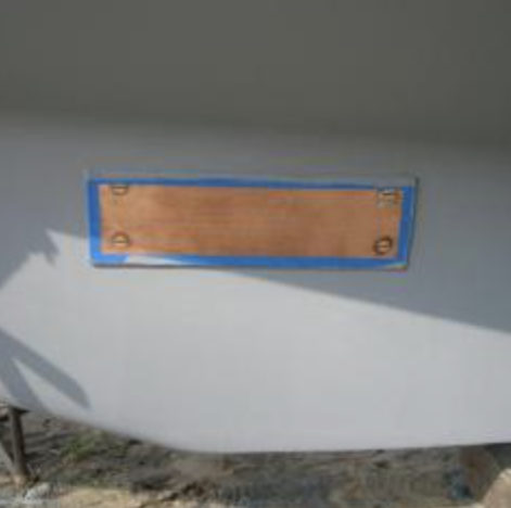
In the center of the plate inscribe the words DO NOT PAINT in letters that are a minimum of one inch high.
Step 6:
Coat the backside of the plate with sealant and install – Wash the plate, the fasteners and the hull surface with mineral spirits. Blow dry with compressed, oil-free air or blot dry with a lint-free rag. Do not drag the rag over the profiled surface as this may deposit rag material.
This surface must be absolutely clean, dry and free of contamination, oil, wax, dust or grease. Even oil from your fingers will contaminate this surface, so avoid touching the prepared plate. Apply a liberal amount of bedding compound to the backside of the plate and spread evenly using a clean putty knife or plastic resin spreader.
Hold the plate up to the hull, push the welded fastener through the hull first and then place each of the additional fasteners through their respective holes (an assistant inside should be ready to receive these, placing a flat washer, lock washer and nut onto each one as they come through).
Torque all of the fasteners to obtain ample sealant squeeze out. Clean all excess sealant using a resin spreader first, DO NOT USE ALCOHOL TO CLEAN EXCESS SEALANT it will inhibit the curing process of polyurethane sealant, then you may use mineral spirits to remove any remaining sealant. This will keep water from finding a path behind the plate or to the weld.
The edge of the plate should be exposed, do not form a fillet with the sealant. There should be no voids visible between the plate and the hull, any gaps between these two surfaces must be completely filled with sealant. Once the sealant has cured fully, torque the fasteners once again.
Step 7:
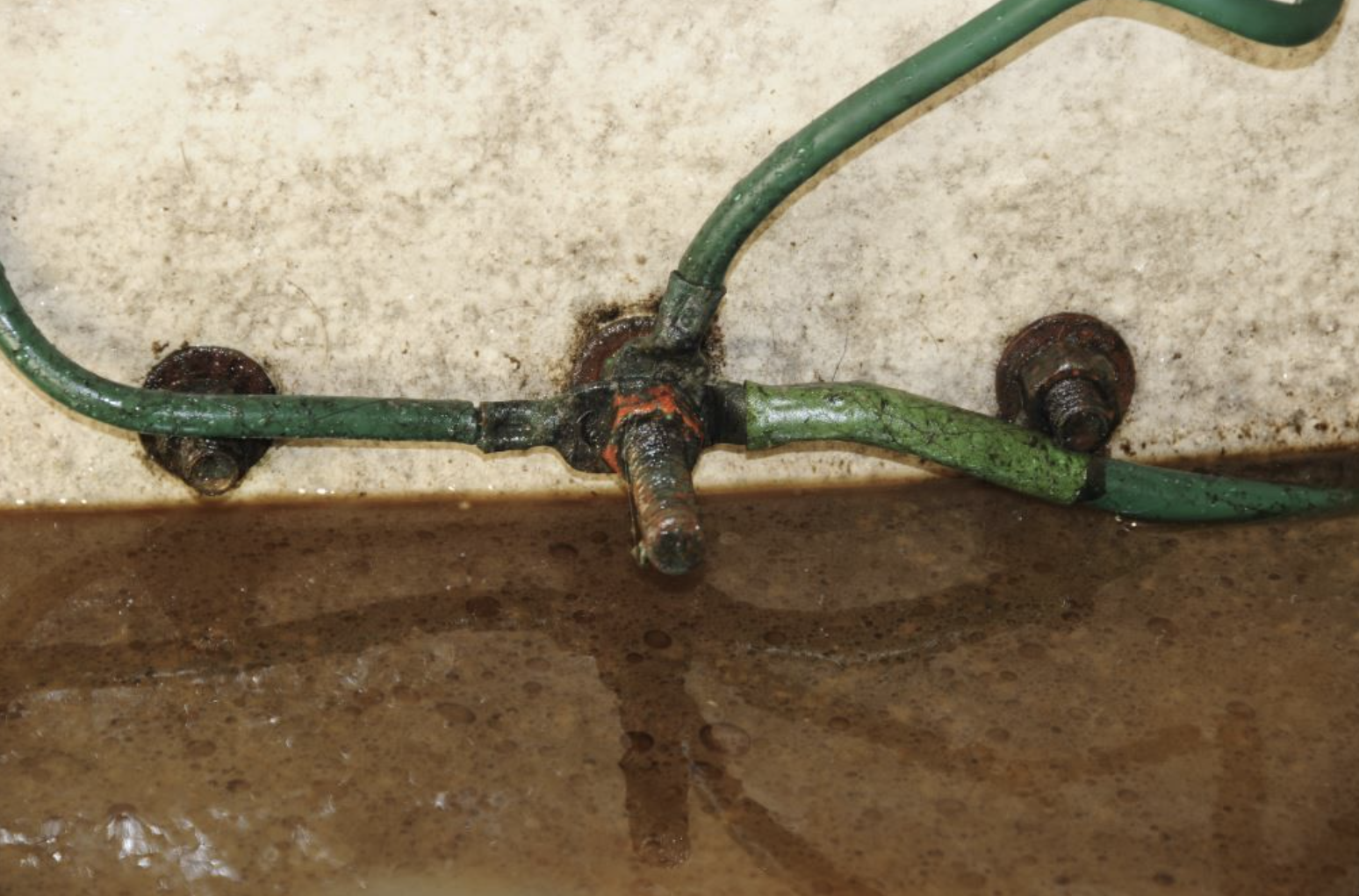
Connections – Affix or tether an engraved or laminated placard with the words MAKE ALL CONNECTIONS TO THIS STUD adjacent to the welded fastener inside the boat. While the physics of this are somewhat complex, and it varies, radio frequency and lightning current that flows to a grounding plate does so primarily on the surface of any wires that are attached to it.
Therefore, unless wires are a very large gauge, they have little effectiveness. Cabling used for lightning connections should be large, #4 AWG (21.2 mm2) for primary and #6 AWG (13.3 mm2) for secondary conductors, tinned and stranded, and run as straight (and as vertical as practical for the primary conductor), and directly to the welded fastener as possible, with as few bends as possible, particularly for the primary down and/or mast connection.
Make sweeps as opposed to sharp 90° turns. Solderless terminals should eb closed end and heat shrunk to keep bilge water at bay. Once connections are complete, spray with a corrosion inhibitor, one that will not wash off easily, such as CRC Heavy Duty Corrosion Inhibitor.
SSB connections should be made solely with copper ribbon or foil, with a minimum thickness of 1/20” (1.27 mm), that is attached to the welded stud, contact surfaces of all connections should be coated with conductant and clamped tightly between two copper nuts and washers (pure copper has greater conductivity than bronze so ideally these should be used; bronze nuts, washers and lock washers may be used first, to physically secure this and all other studs, these fasteners should not have to be disturbed for making electrical connections).
Once the vessel is launched, check for leaks and perform radio checks and a standing wave ratio test if an SSB has been connected to the grounding plate. All fasteners exposed to seawater, including the bilge, must be bronze, not brass.