The Importance of Valve Adjustment: Keeps a Diesel Running Smoothly
Diesel engines are legendary for their reliability, durability and economical use of fuel. There is, however, a price to be paid for these attributes. Diesel engines are typically heavier than their gasoline brethren and they are also more costly to produce as a result of the robustness of the components (required for higher compression), and finer tolerances, particularly in the fuel delivery system, often measured to the ten-thousandth of an inch.
Required Maintenance
There’s one maintenance item that will if deferred, quickly negate many of a diesel engine’s virtues. Valve adjustment is critically important to every four-cycle engine’s operation (virtually all modern inboard diesels are four-cycle, with the legacy Detroit Diesels being an exception), yet it is also among the most frequently overlooked or forgotten tasks. In many cases, if an engine continues to run and appears to be delivering reliable service, then the perception is that it needs no maintenance, service or adjustment, yet nothing could be further from the truth.
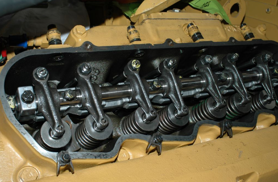
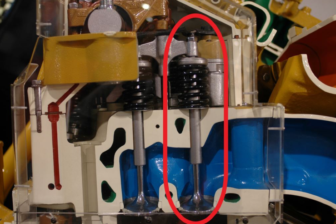
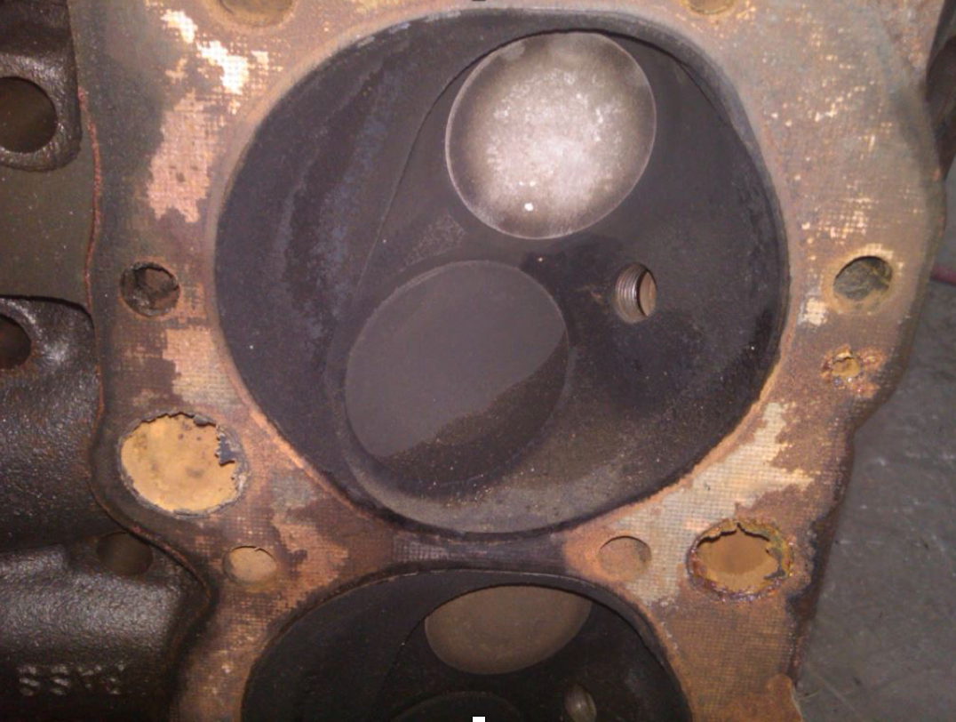
Intake and exhaust valves live and work within an engine’s cylinder head, that four- or five-inch-thick hunk of iron or aluminum that’s bolted to the top of the block. Valves, which are vaguely mushroom-shaped, are actuated or opened and closed through a combination of action from the camshaft and valves springs. The former opens the valves by either lifting a pushrod and rocker arm or, in the case of an overhead cam, by acting directly on the rockers (or “tappets” if you are from the UK or Commonwealth) while the latter draws them shut again through spring tension.

Typically, it’s a delicate, precise operation that occurs at eye-blurring speed. If you’ve ever had the opportunity to see this mechanical choreography in action, while an engine is operating with the valve cover removed, it’s difficult not to be impressed with its oleaginous precision.
If, on the other hand, the balance and precision are removed from a valve train (the valve train consists of all of the moving parts associated with valves, lifters, pushrods, springs, rocker arms and the valves themselves), then chaos quickly ensues. The opening and closing of the valves allow fresh air to enter the cylinder, to facilitate the combustion process, and exhaust gasses to exit once the power has been produced and the burn sequence is complete, while both valves remain closed tight during the compression and power strokes).
Tight Tolerances
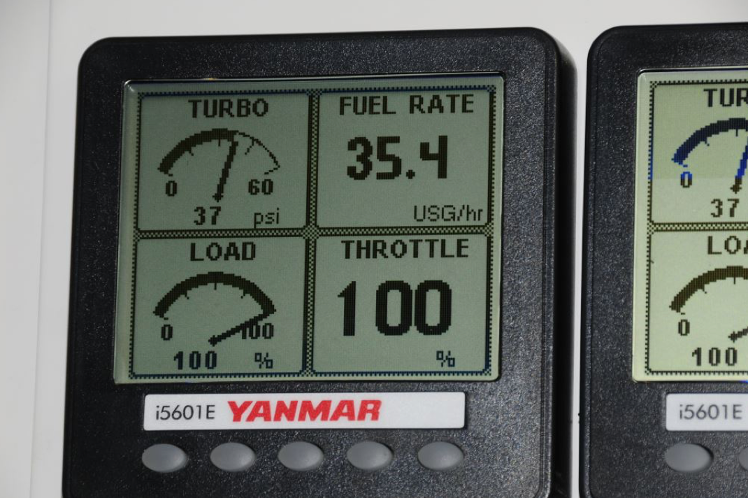
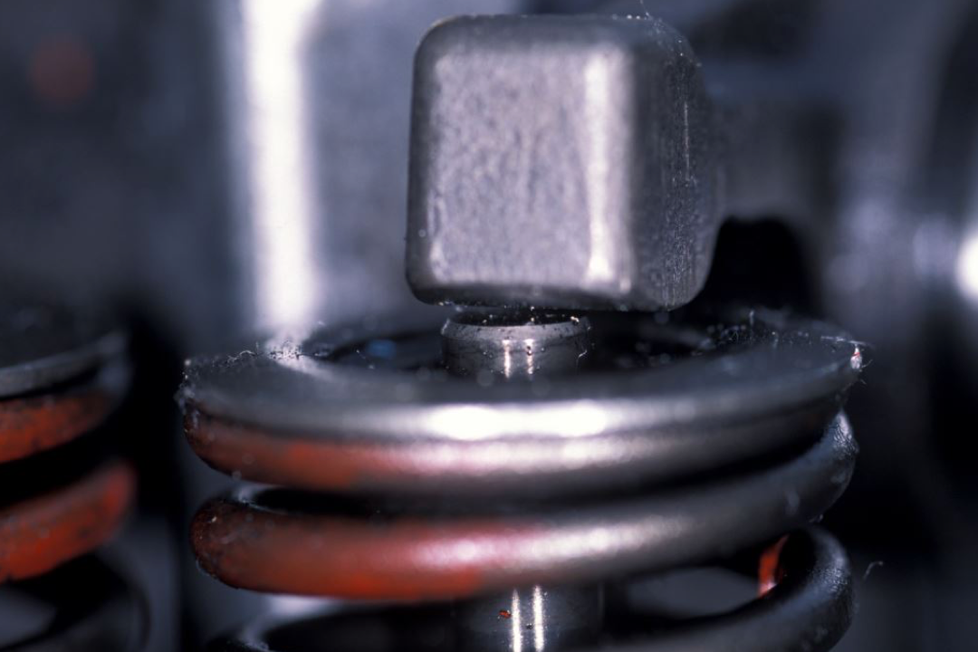
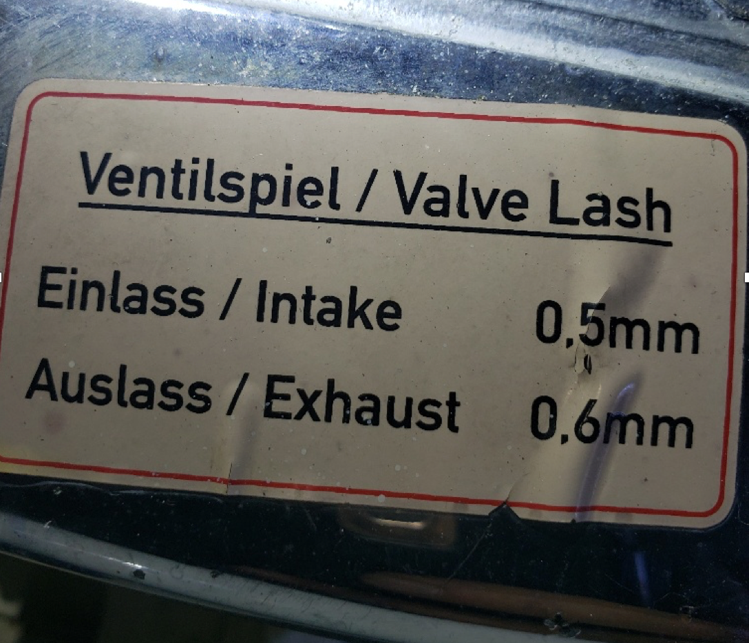
If the clearance between the valve stem and the rocker is not within the engine manufacturer’s tolerance, then the valve will either open too far, or not far enough, and it may stay open too long, or not long enough. Any of these scenarios plays havoc with an engine’s operation, upsetting efficiency, power output and fuel economy as well potentially damaging components, and making starting more difficult, and/or producing excess smoke.
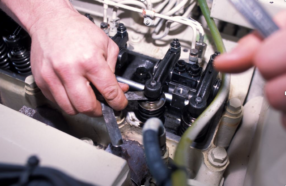
If the valve train is upset or removed for any reason, or if the cylinder head is removed or re-torqued, the valves must be adjusted. Adjustment requires clear understanding of the procedure (experience helps, but it’s not necessary, provided you follow the service manual instructions) as well as the ability to use feeler gauges and a wrench. Each valve is adjusted by rotating the engine until a specified valve is closed and its associated piston has traveled to the top of the cylinder (all valve adjustment is carried out with the engine off, however, the engine must be rotated, usually using the starter or a rotating bar, until the piston and valves are in the correct position — the engine cannot and must not be started during the procedure).
The correct clearance varies from engine manufacturer to engine manufacturer and sometimes between intake and exhaust valves, however, it is usually in the region of ten or twelve-thousandths of an inch, expressed numerically as 0.010” or 0.012” (a credit card, by comparison, is about 30 thousandths of an inch thick). Make certain you are observing the proper units, manuals often provide the clearance in inches and millimeters.
Correct Procedure
Valves are adjusted in a specific sequence that is detailed in the service manual; however, no valve can be adjusted unless the valve itself is completely closed. That is, the spring is lifting the valve fully into its seat in the cylinder head. If the camshaft is acting on the valve or valve train in any way, then it cannot be properly adjusted.
Provided the access is good, i.e. there’s adequate room above the engine to remove the valve cover and get tools and one’s head into the area, valve adjustment usually takes no more than a few hours, however, its value is incalculable. For most engines, the tools required for this task are simple, a set of combination wrenches (you’ll likely use the box end), a screwdriver and a means of rotating the engine, again sometimes the starter and in other cases a tool that’s used to rotate the engine via the fly wheel, or a breaker bar and socket on the crankshaft pulley nut, often called “barring” the engine over. The most important tool in this process is a set of feeler gauges. These are common and inexpensive; however, my preference is for a variety that is less common, one called a “go-no go” feeler gauge.
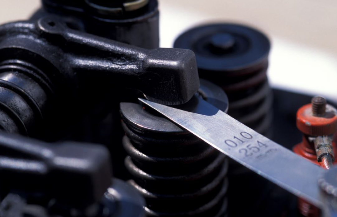
Common feeler gauge sets are made of a series of precision, flat steel plates, each a different thickness. A go-no-go gauge utilizes a stepped plate, the tip being slightly thinner than the shank, thereby aiding the user in gauging clearance, the thinner part should slide into the gap with slight resistance, while stopping at the step. If the thicker stepped portion fits into the gap as well, the clearance is too great. For marine use, if you can find them, stainless feeler gauges are preferred, otherwise, make sure they are well oiled as they are highly prone to turning into a block of rust while in your toolbox. To reiterate, during the adjustment process, the engine must be disabled so that it cannot start.
If valve adjustment is carried out at the manufacturer’s specified intervals, it will ensure economy and efficiency. If your engine and genset call for periodic valve adjustment, and you don’t know when they were last adjusted, don’t take chances, at the very least check the clearances.
By Steve D’Antonio
Beginning his career in 1988, as a marine mechanic, electrician, manager and partner of a custom boat building shop and two boatyards and technical journalist, as well as through Steve D'Antonio Marine Consulting, Inc, Steve provides personalized and hands-on service to boat buyers, boat owners, boat builders and equipment manufacturers, as well as others in the marine industry around the world. Steve is an American Boat and Yacht Council Certified Diesel, Electrical, Corrosion and Systems Master Technician/Adviser. To learn more or to contact Steve, go to SteveMarineConsulting.com